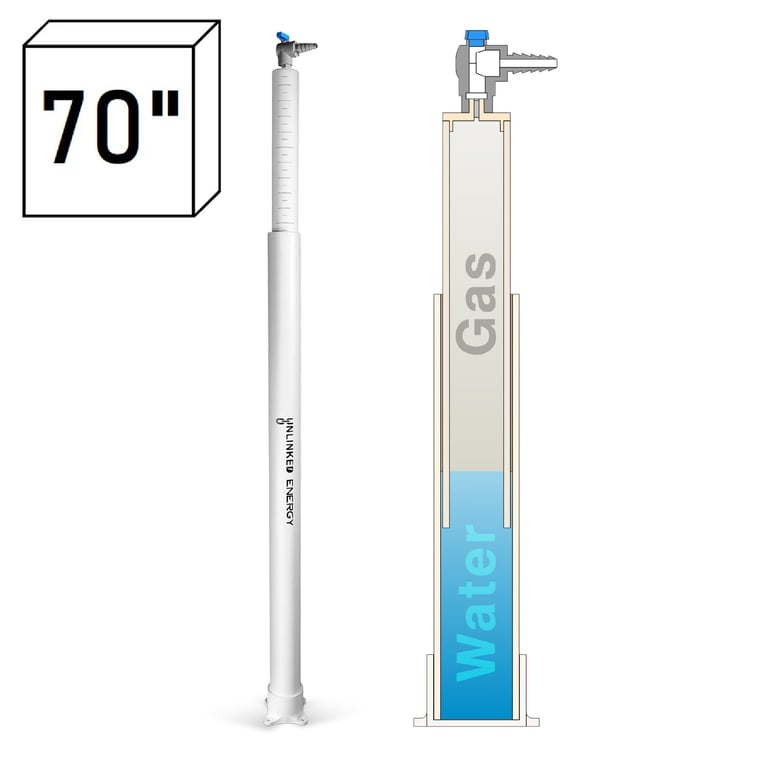
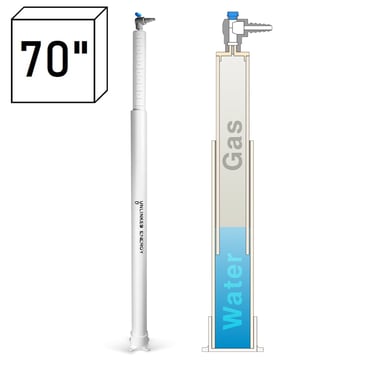
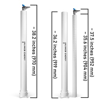
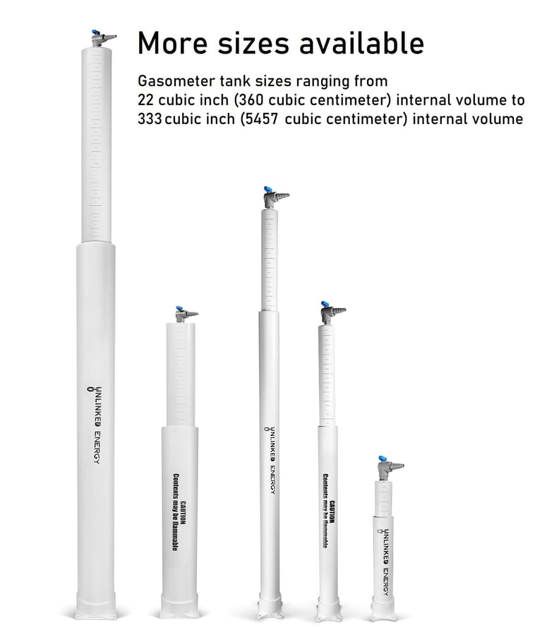
A gasometer tank (or gas holder) is made of two parts, the upper lift and the lower reservoir.
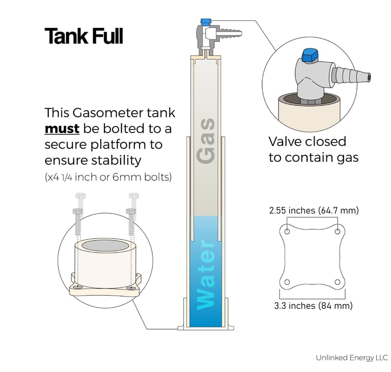
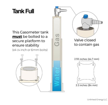
This gasometer tank must be bolted to a secure platform to insure stability. Use four 1/4 inch or 6mm hardware (not included).
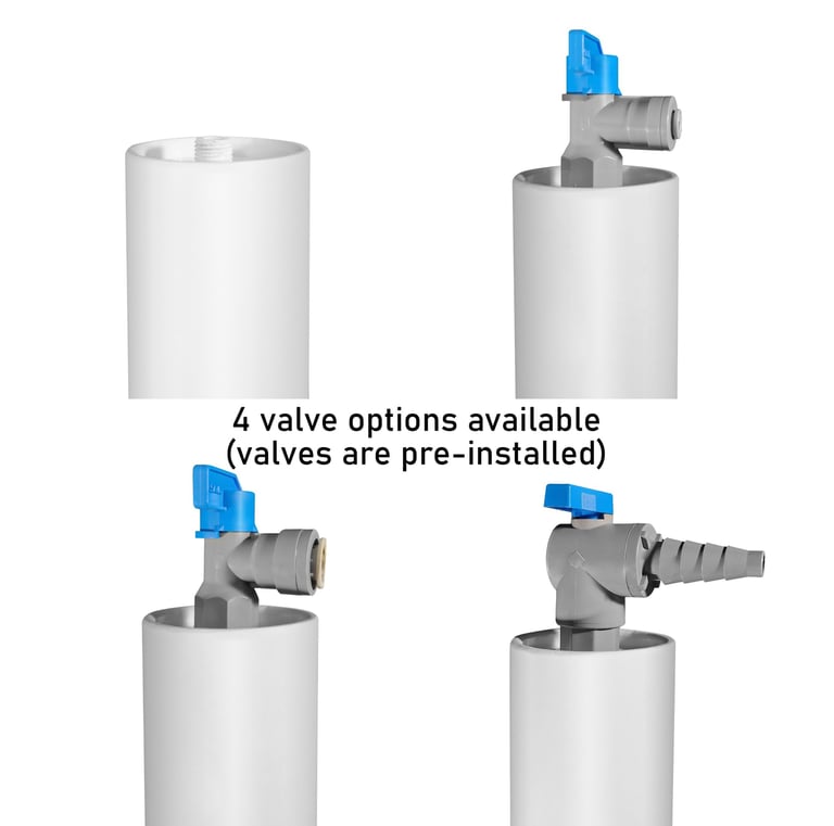
Place the upper lift (with a properly installed valve) into the lower reservoir, and fill the reservoir with clean water.
Fill, store, and discharge operation:
Connect your supply hose onto your valve and turn the valve to the open position.
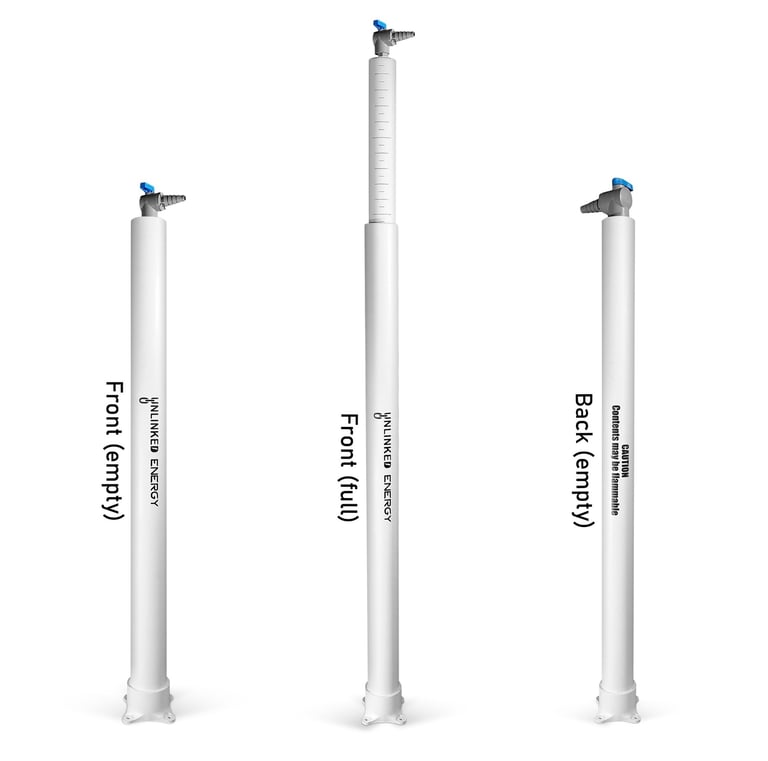
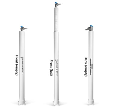
The lift can then be filled with up to 70 cubic inches (1147 cubic cm) of gas. The inflow of gas into the lift will create buoyancy, causing the lift to rise.
Caution: If the amount of gas inside the lift exceeds its rated internal volume (70 cubic inches or 1147 cubic cm in this case), the gas will begin to flow under the lift and out into the surrounding area.
Once filled with gas, the valve can be turned to the closed position, and the hose disconnected.
Connect the demand hose to the valve and open the valve as needed to release the gas. Once the gas inside the lift is depleted, or the valve is closed, the flow of gas will cease.
Supply and demand balancing:
If you are using the gasometer tank (gas holder) for supply and demand balancing purposes, cut your supply-to-demand hose/line and install a T intersection fitting/connector in place. Then install another hose onto the third intersection/connection/fitting point and connect that hose to the valve on the gasometer tank. Turn the valve to the open position to allow access pressure (gas) to flow into and out of the tank during supply and demand fluctuations. When supply outpaces demand, gas will flow into the upper lift, creating buoyancy causing the lift to rise.
Caution: If the amount of gas inside the lift exceeds its rated internal volume (70 cubic inches or 1147 cubic cm in this case), the gas will begin to flow under the lift and out into the surrounding area.
When demand begins to outpace the supply, the lift will begin to lower or fall. The lift will fall until supply balances with demand or until all gas inside is depleted.